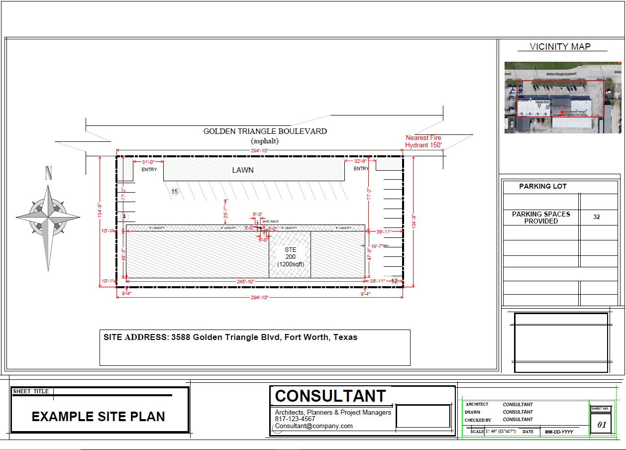
Building plans are a graphical representation of what a proposed building will look like after construction. They are typically used by builders and contractors to construct buildings and can include site plans, foundation plans, floor plans, and building elevations and many others. Anyone who is constructing a new building, adding on to an existing building, remodeling an existing building, changing the occupancy and use of an existing building or space will need to submit building plans for review.
For buildings over 5,000 square feet, state law requires that structural, mechanical, electrical and plumbing plans be sealed by a Texas Professional Engineer. This requirement applies even if the tenant or work area is less than 5,000 sf, but the building itself is over 5,000 sf.
Complete set of building plans
All plans should be drawn to scale and will include:
Site Plan showing:
- Existing and/or proposed structure(s) with exact dimensions
- Parking areas and required number of parking spaces
- Driveway locations and traffic circulation system
- Lot and building line dimensions, as well as dimensions from property line to the project
- Alley with dimensions, if applicable
- All easements, if applicable
- Street names
- Sidewalks
- Bike rack locations
- Location of nearest fire hydrant(s)
- Fire lanes
- Utility or civil engineering site plan, showing water and sanitary sewer

Landscape Plan showing:
Not required for additions less than 3,000 square feet or 30 percent of existing building footprint
- Calculation of net site area showing all existing and proposed structures, parking and access, other paved areas, and all required buffer-yard areas.
- Calculation of required landscape area
- Location and dimensions of areas to be landscaped and total amount of landscaped area
- Location, number and planting size of all shrubs, and ground cover including both required and
- actual materials provided;
- Location and coverage of required irrigation system
- Delineation of artificial lot, if applicable, including depiction of all proposed and existing structures, access drives, appurtenant parking and other paved areas proposed for expansion or new construction.
Building Plans showing:
- Floor plans showing all rooms and spaces with dimensions & labels identifying the nature and use of each.
- Location of any existing or proposed fire walls, fire barriers, horizontal assemblies, fire partitions, or smoke partitions and associated wall details and UL assemblies.
- Location and dimensions of all portions of the exiting system including window and door schedules.
- Method of construction and types of construction materials.
- Exterior wall envelope details, window and doors including any associated fire ratings, eaves or parapets, and means of drainage.
- Handicap accessibility provisions
- Foundation plans if not part of a comprehensive structural package.
Mechanical plans showing:
- Equipment schedule with supply and outside air capacity
- Supply and return duct material and sizes.
- Ventilation calculations showing compliance with section 403 or engineer's statement of compliance with ASHRAE 62
- See energy code section for additional requirements
- Engineered design is required for buildings over 5,000 sf.
Electrical plans showing:
- Transformer, disconnect, meter, and panel locations.
- Wire sizes and locations --- one line diagrams.
- Lighting and switching diagrams (see energy code section for additional requirements)
- Sufficient information to determine compliance with electrical code
- Engineered design is required for buildings over 5,000
Plumbing plans showing:
- All fixture locations and spacing
- Supply and waste piping sizes --- one line diagrams.
- Any specialty devices (grease traps, neutralizers, backflow preventers, etc…)
- Sufficient information to determine compliance with pluming code.
- Engineered design is required for buildings 5,000 sf.
Energy Code information throughout plans:
- Insulation materials and their R-values
- Fenestration U-factors and SHGC's
- Area-weighted U-factors and SHGC calculations
- Mechanical and service a water heating system and equipment types, sizes and efficiencies;
- Economizer description --- required for any system over 54,000 btu/4.5 tons
- Equipment and systems controls
- Duct sealing, duct and pipe insulation and locations
- Lighting fixture schedule with wattage and control narrative
- Duplicate lighting floor plan identifying the various daylight zones and the lights designated for each zone and how they will be grouped or independently switched. (commercial only)
Helpful Information
The rules for engaging a registered architect are defined by The Texas Board of Architectural Examiners.
The rules for engaging a registered engineer are defined by The Texas Board of Professional Engineers.
Plans that are not required to be drawn by licensed professionals may be drawn by the applicant, a designer, draftsman or any other qualified person.
Plans should be drawn to scale. A typical building plan scale is 1/8 inch equals 1 foot.
Plans should be sizes to allow all information to be easily read. A typical plan sheet size is 24 inches tall by 36 inches wide but larger and smaller sizes are acceptable.